Intravascular ultrasound artifacts in coronary stent assessment
An IVUS frame can make a well-expanded stent look incomplete, or hide a real gap between struts and the vessel wall. The failure point is interpretation: metal, calcium, catheter rotation and trapped air all alter the signal before it reaches the display.
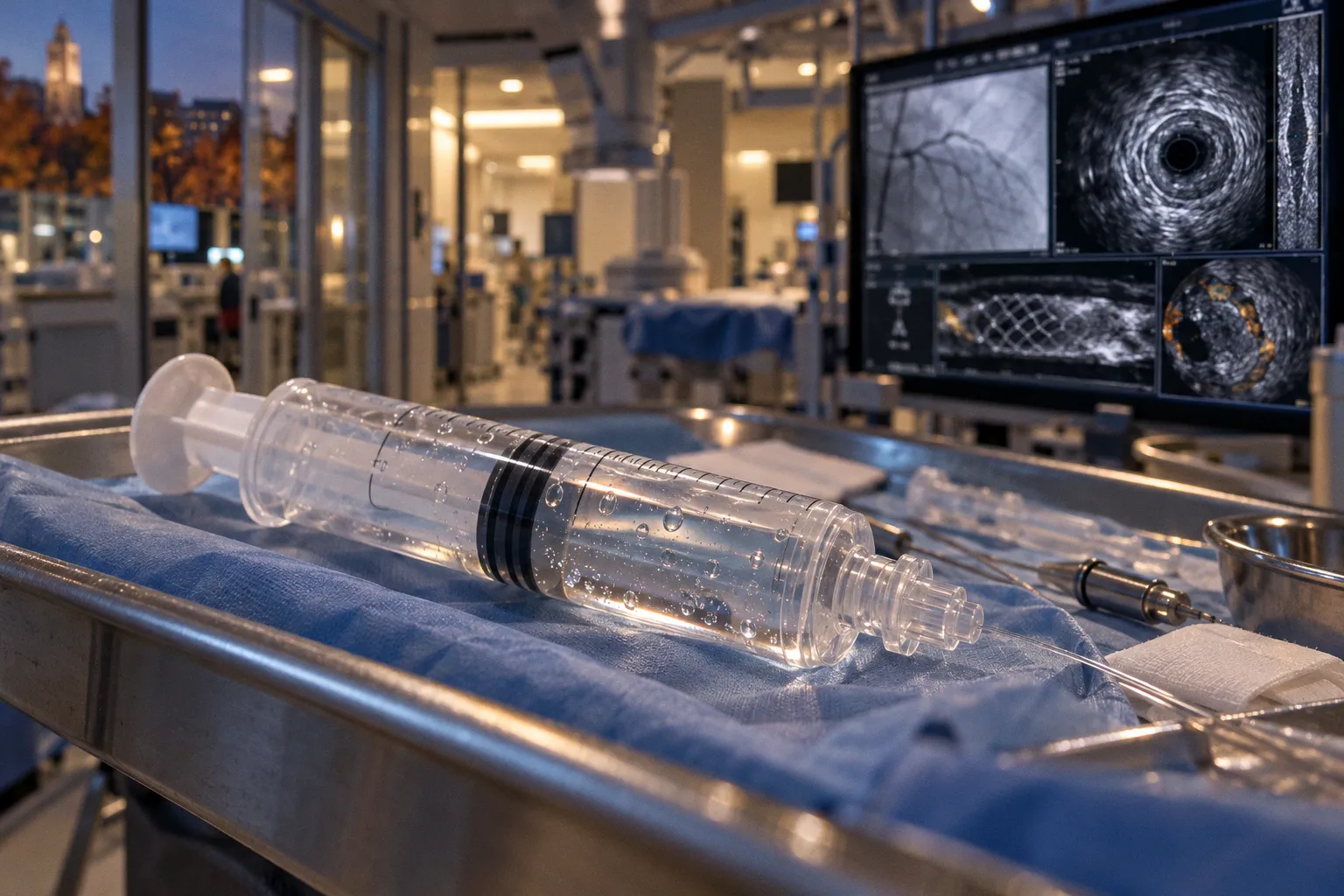
These intravascular ultrasound imaging artifacts in coronary stenting can obscure the very geometry the operator needs to assess.
The useful question is mechanical. Does the finding persist across adjacent frames and pullback, and does its shape fit a known artifact? A dark region behind a strut may be acoustic shadowing. A repeating geometric distortion may be rotational. A suspected malapposition should be judged from visible strut-to-wall relationships, not inferred through signal that the catheter cannot transmit.
First separate wall contact from signal loss
Stent malapposition means a strut is separated from the vessel wall. IVUS can show the lumen, wall and stent structure in cross-section, but it cannot reconstruct tissue hidden behind a strong reflector. Metallic struts and dense calcium block ultrasound transmission, producing post-acoustic shadowing. The shadow is an information gap, not evidence that the vessel wall or tissue behind it is absent.
This distinction matters most when the apparent gap sits beside a strut with a dark sector beyond it. The operator can identify the strut where it is visible. The operator cannot use the shadowed sector to confidently locate the wall. Calling that sector malapposition converts a known limitation of the signal into a structural diagnosis.
A practical reading sequence keeps the interpretation tied to observable geometry:
1. Locate the catheter and lumen. Check whether the near-field image is clean enough to define the lumen boundary. Ring-down or air-related reflection can corrupt this region before the stent is assessed.
2. Identify visible struts. Look for bright metallic reflections and note where their acoustic shadows begin. Do not treat the shadow as a continuation of the strut or as a view of the vessel wall.
3. Trace the wall where the signal remains interpretable. Compare the position of visible struts with the visible wall around the circumference. A gap is meaningful only where both boundaries can be assessed.
4. Follow the finding through the pullback. A structural relationship should be coherent across neighboring frames. A single distorted frame is weak ground for a geometric conclusion.
5. Check for a mechanical pattern. Cyclic distortion suggests non-uniform rotational distortion in a mechanical catheter. Repeated echoes behind dense structures suggest reverberation. These patterns have different causes from malapposition.
A shadow marks where ultrasound information stops. It does not mark where the vessel wall stops.
This approach does not eliminate ambiguity. Some metal-related shadowing is inherent to ultrasound interaction with stent struts. No operator maneuver can recover tissue detail that the beam never traversed.
Mechanical rotation can bend the geometry
Non-uniform rotational distortion, or NURD, occurs in mechanical IVUS systems. Friction during transducer rotation can disrupt the regular sweep, particularly when the catheter passes through tortuous or severely bent segments. The result is cyclic geometric distortion: structures may appear displaced or stretched around the circumference.
NURD is an image-formation problem. A strut that appears to move relative to the wall in a distorted frame may not represent a change in apposition. The rotation itself may be irregular. This is why an operator should inspect the pattern across the sequence rather than treating each cross-section as an independent measurement.
When the image geometry looks unstable, use this troubleshooting order:
- Review consecutive frames for a repeating or cyclic deformation.
- Relate the distortion to vessel tortuosity or a sharply bent catheter course.
- Avoid measuring a suspected gap from a frame whose circumferential geometry is visibly unreliable.
- Reassess the same segment in adjacent frames and distinguish persistent anatomy from rotation-linked displacement.
NURD is specific to mechanical IVUS systems. A phased-array catheter does not rely on a rotating transducer in the same way, so this particular mechanism does not apply. That does not make phased-array imaging artifact-free; it changes which technical limitations are relevant.
Pullback adds another layer. Automated IVUS pullback commonly proceeds at about 0.5 mm/s. That is a controlled sampling speed, not a guarantee that every frame is diagnostically clean. A sequence can still contain rotational distortion or acoustic obstruction. The pullback provides continuity; the operator still has to judge whether the geometry is credible.
Metal and calcium create shadows and repeated echoes
A metallic stent strut reflects and attenuates the ultrasound beam. Heavy calcified plaque can do the same. Behind either structure, post-acoustic shadowing blocks the view of deeper tissue. In a stented segment, shadowing may conceal the wall that would otherwise help establish whether a strut is apposed.
Reverberation has a different appearance. The beam reflects repeatedly between strong interfaces, producing multiple, roughly equidistant parallel echoes behind dense structures such as metal struts or heavy calcium. Those repeated lines are not multiple layers of vessel anatomy. They are echoes generated by repeated reflections.
| Image finding | Likely mechanism | What it limits | Interpretation |
|---|---|---|---|
| Dark sector behind a strut or dense calcium | Post-acoustic shadowing | Tissue and wall visibility behind the reflector | Treat the sector as obscured, not as proof of malapposition |
| Multiple parallel echoes at regular spacing behind a strong interface | Reverberation | Clear definition of structures behind the reflector | Do not count repeated echoes as separate anatomic boundaries |
| Bright concentric rings near the catheter | Ring-down artifact | Near-field lumen and adjacent detail | Resolve catheter-related interference before judging nearby stent geometry |
| Cyclic circumferential deformation in a mechanical system | NURD | Reliable angular position of structures | Confirm the finding across the sequence; avoid relying on distorted frames |
These artifacts can coexist. A strut may produce both shadowing and reverberation. Calcium can add another strong reflector near the stent. The image may therefore show a real metallic boundary while concealing the tissue needed to interpret its relationship to the vessel wall.
That combination is a common source of IVUS image interpretation challenges. The remedy is disciplined classification. Identify the visible reflector, identify the region where signal is blocked, and state what cannot be resolved. A confident label does not make a hidden boundary visible.
Near-field interference and air bubbles
Ring-down appears as bright concentric rings around the IVUS transducer catheter. Because it occupies the near field, it can obscure the lumen and adjacent vessel detail. If the artifact overlaps the area used to define the lumen boundary, an apparent strut-to-wall distance may be unreliable.
Air inside the IVUS catheter is more disruptive. Unremoved air bubbles cause strong acoustic reflection and can severely degrade the image, sometimes to the point that the ultrasound view is largely obscured. This is a catheter-preparation problem rather than a feature of the coronary anatomy.
When image quality deteriorates close to the catheter, the sequence should be straightforward:
- Determine whether bright rings are centered on the transducer and consistent with ring-down.
- Consider trapped air when reflection is severe or broad enough to degrade the overall image.
- Re-establish a usable image before making measurements that depend on the lumen or near-field boundary.
- Keep residual uncertainty explicit if the affected region remains unreadable.
This is particularly relevant when assessing stent edges. Edge interpretation depends on distinguishing the end of the metal scaffold from vessel boundaries and nearby tissue. Near-field interference can obscure those relationships. A bright ring or disrupted boundary at an edge should not automatically be assigned to tissue, dissection or strut position.
The term intravascular ultrasound edge artifacts can refer to several different appearances, so the mechanism matters. A dark area behind metal is a transmission limit. Repeated lines suggest reverberation. Concentric near-field rings point toward ring-down. Cyclic distortion in a mechanical system raises concern for NURD. Grouping all of them as poor image quality loses diagnostic information.
Choose the system with its limits in view
Mechanical rotational and phased-array IVUS systems form images differently and operate at different frequencies. Conventional mechanical rotational catheters generally use 40–45 MHz; high-definition mechanical systems can reach 60 MHz. Solid-state phased-array probes typically operate at 20 MHz.
Conventional IVUS systems have typical axial resolution around 80–100 µm. High-definition systems operating at 60 MHz can provide axial resolution below 40 µm. Modern thin-strut coronary stents commonly have strut thicknesses around 60–80 µm. Those values describe different properties: system resolution is not a direct guarantee that every individual strut or tissue interface will be cleanly separated on every frame. Image quality still depends on signal transmission, catheter position and the presence of artifacts.
| System characteristic | Mechanical rotational IVUS | Phased-array IVUS |
|---|---|---|
| Typical frequency | 40–45 MHz; up to 60 MHz in HD systems | About 20 MHz |
| Image formation | Rotating transducer sweeps the vessel circumference | Solid-state array generates the image |
| Relevant mechanical issue | Friction-related NURD in tortuous or sharply bent segments | NURD mechanism does not apply in the same way |
| Shared limitation | Metal and dense calcium can shadow deeper structures | Metal and dense calcium can shadow deeper structures |
Higher frequency can support finer axial resolution, but it does not repeal acoustic shadowing. A 60 MHz image can still lose tissue detail behind metal. A 20 MHz phased-array image can still be compromised by air bubbles or strong reflectors. System selection should therefore account for the anatomy and the specific imaging task, while interpretation should remain anchored to what the frame actually shows.
For PCI troubleshooting, the operational sequence is more useful than a generic preference for one catheter type: identify the artifact, determine whether it affects the boundary needed for the decision, then decide whether the remaining image supports measurement. If it does not, do not convert a technical limitation into a precise apposition claim.
A disciplined read for stent assessment
The main IVUS pitfalls in PCI cluster around four questions: Is the lumen boundary visible? Is the strut visible? Is the wall visible beside it? Is the frame geometry stable? A negative answer to any of these limits what can be concluded about apposition.
Use the image in layers. First assess near-field quality and catheter-related interference. Then identify stent struts and the shadows they cast. Next assess wall contact only in sectors where both the strut and wall can be seen. Finally, compare adjacent frames and check whether mechanical rotation has distorted the geometry.
Measure what is visible. Classify what is distorted. Leave the rest unresolved.
IVUS remains useful because it shows coronary vessel and stent structure during PCI. Its value depends on separating anatomy from the effects of the imaging system. When a suspected gap persists across interpretable frames and both boundaries are visible, it can support an assessment of malapposition. When metal shadowing, reverberation, ring-down, air or NURD removes the boundary or distorts its position, the finding is indeterminate from that image.
The decision is binary: use a frame for apposition assessment only when the relevant strut, wall and geometry are interpretable; otherwise, do not call the artifact anatomy.